New Case for my BITX40 Radio
Parts: 1 2
My BITX40 needs a proper case. It's an amateur radio transceiver kit for the 40 meter band by Ashhar Farhan VU2ESE. I originally tested the kit by mounting it to an MDF board. It's not very ergonomic nor very portable.
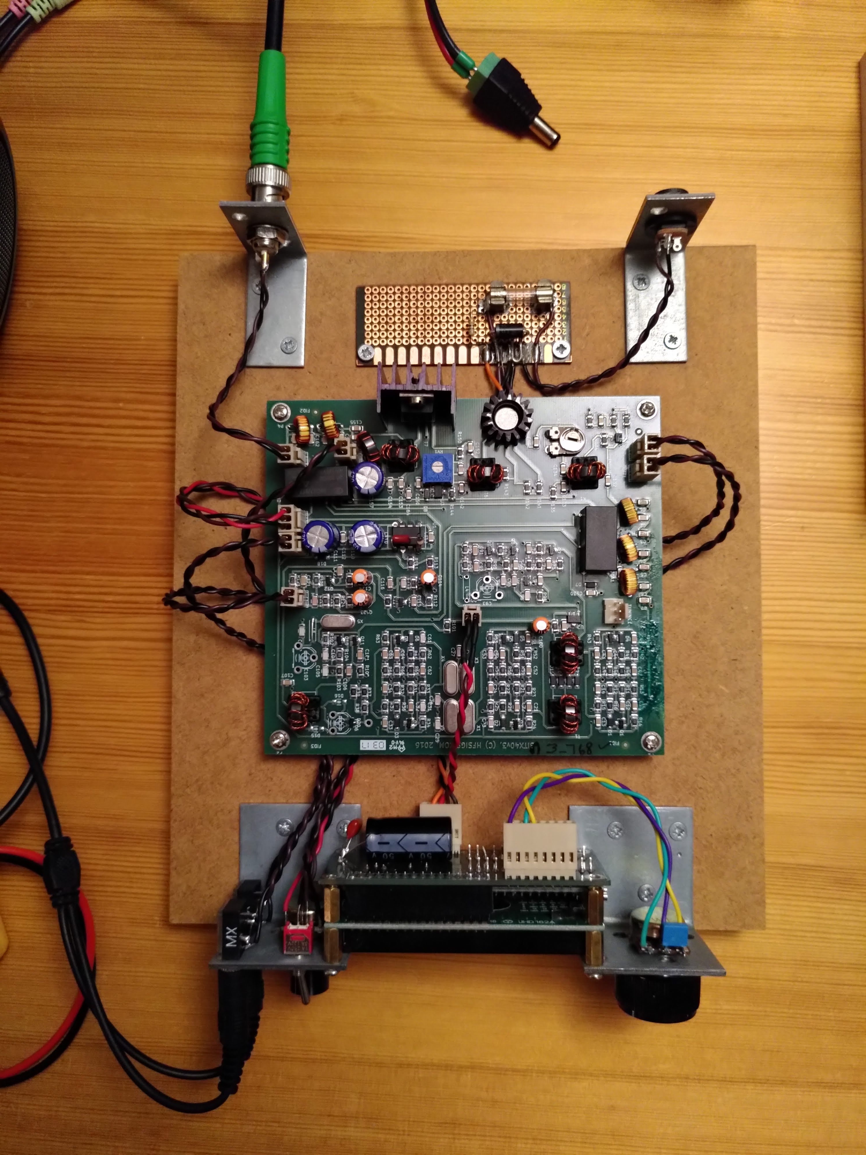
Figure 1. BITX40 test build on an MDF board
I finally decided on a new case: a Bahar BDA 40004-A6(W200). I bought mine on AliExpress. It's very blue! I consider it to be an homage to Pete Juliano N6QW who uses his "Juliano Blue" paint for his homebrewed rigs.
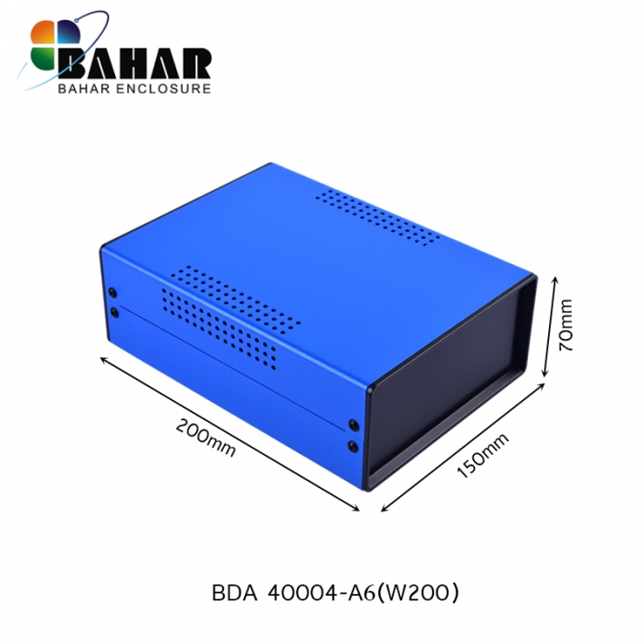
Figure 2. The new Bahar BDA 40004-A6(W200) enclosure
The blue top and bottom parts are made from steel, and the front and back panels are made from black plastic, about 2.5 – 3.0 mm thick. It is all held together with eight screws. The inside of the panel has a convenient 0.5 × 0.5 mm grid.

Figure 3. Back side of one of the plastic panels (unrelated toki pona hieroglyphs in the background)
It took a while to figure out the placement of the components on the front panel. There was not much space left in the end. I cut out the rectangle for the LCD first using a rotary tool and a file. Then I drilled the holes. I don't have a drill stand, so upon close inspection you'll see that the holes aren't lined up perfectly straight.
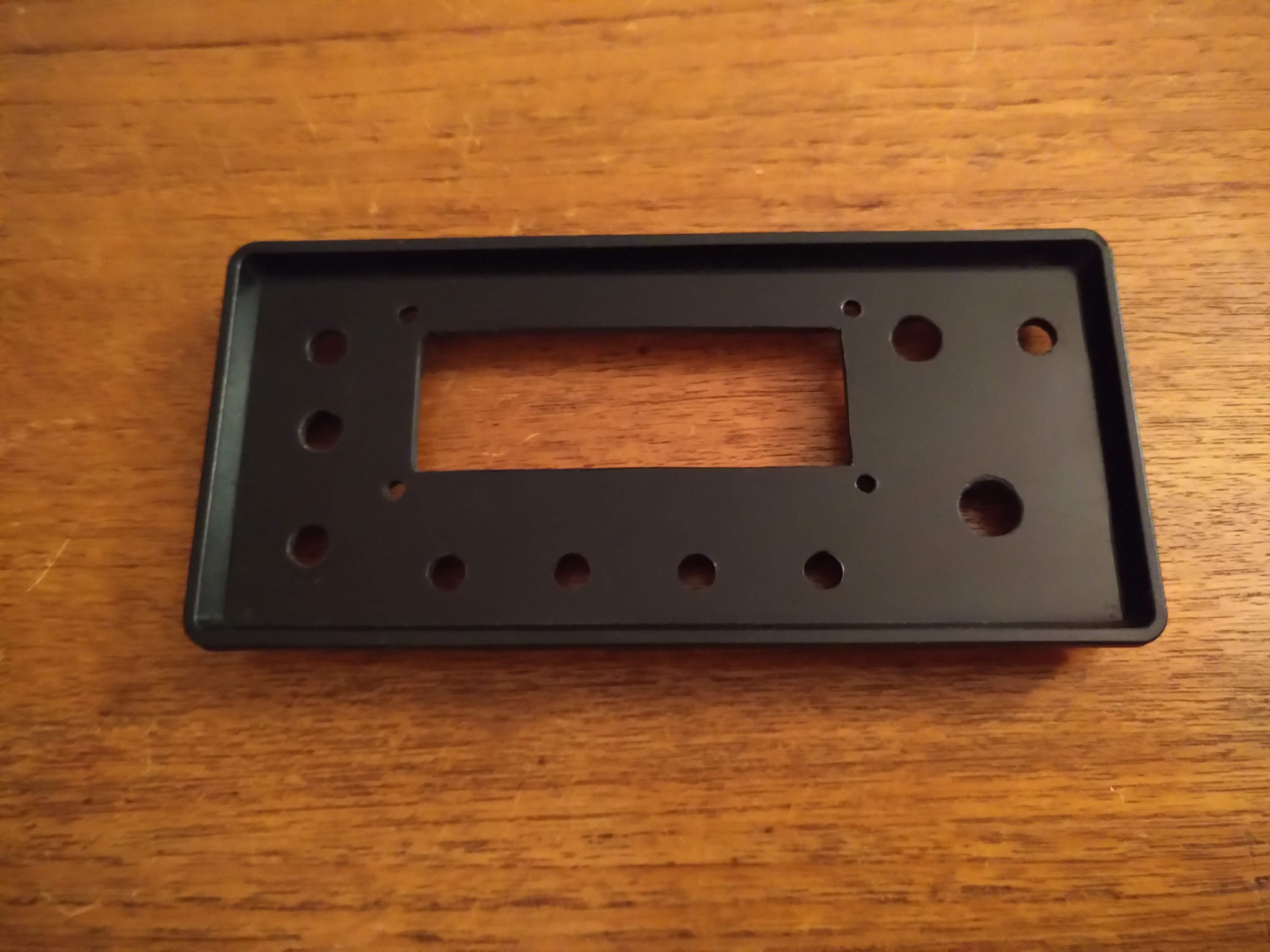
Figure 4. Front panel holes
Of all the components I mounted, I had most problems with the four 3.5 mm jacks. It turns out that most jacks I could find were made for much thinner panels. They were probably made for metal, not plastic. The jacks I got also broke. Maybe the fastening nut deformed, or the threads wore out (I could only use the outermost bit). In any way, some of the nuts popped loose when I tightened them or when I pulled out a plug. I had bought ten of them and ended up using the the four of them that seemed to be intact the most.
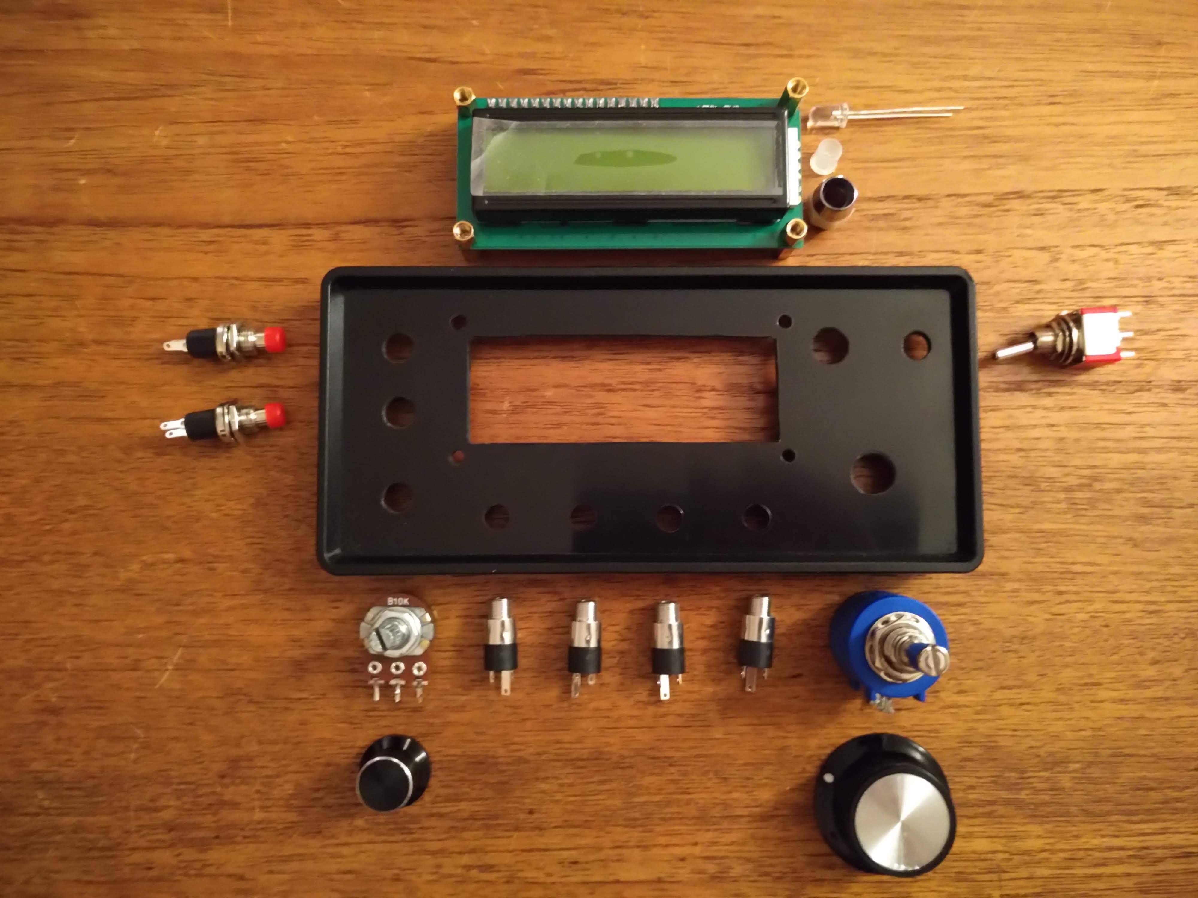
Figure 5. Front panel holes and components
The front panel components are as follows. To the left:
- Top: Function button
- Middle: Fine tune button
- Bottom: Volume knob
In the middle:
- Top: LCD display
- Bottom: 3.5 mm jacks, left to right:
- Headphones
- Microphone
- PTT button
- Iambic key
To the right:
- Top left: TX indicator LED
- Top right: PTT switch
- Bottom: Frequency knob
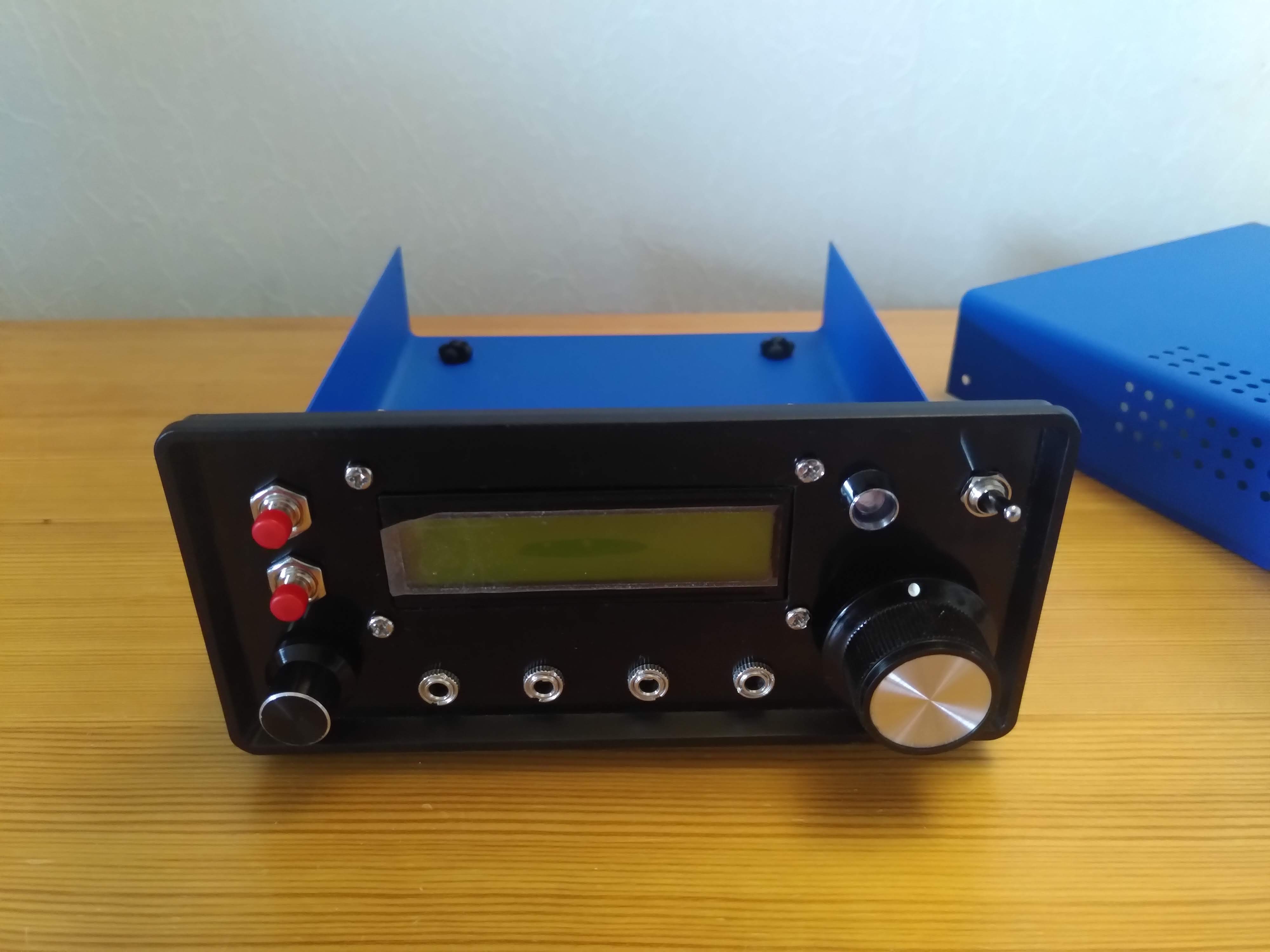
Figure 6. Front panel with components mounted
I tried to place the components so that it would be easy to use both hands simultaneously. I had some uses cases in mind:
- Tuning around and listening. Tune with the right hand, and continuously adjust volume with the left (due to the lack of AGC)
- Talking. Flip the PTT switch back and forth with the right hand, and adjust volume with the left.
- Fine-tuning and adjusting settings. Hold the fine tune button (or press the function button) with the right hand and adjust the tuning knob with the right.
I added extra room between the PTT switch and the tuning knob. It was barely enough. If the switch is in the down position it is slightly in the way. Originally, I wanted "up" to be "transmit" (as in, the signal goes up into the air), but I now I'll make "up" be "receive" so that the switch is least in the way while tuning.
Next I drilled four holes in the bottom side for M3 screws. The case has rubber feet that conveniently keep the screw heads from touching any surface the case stands on.
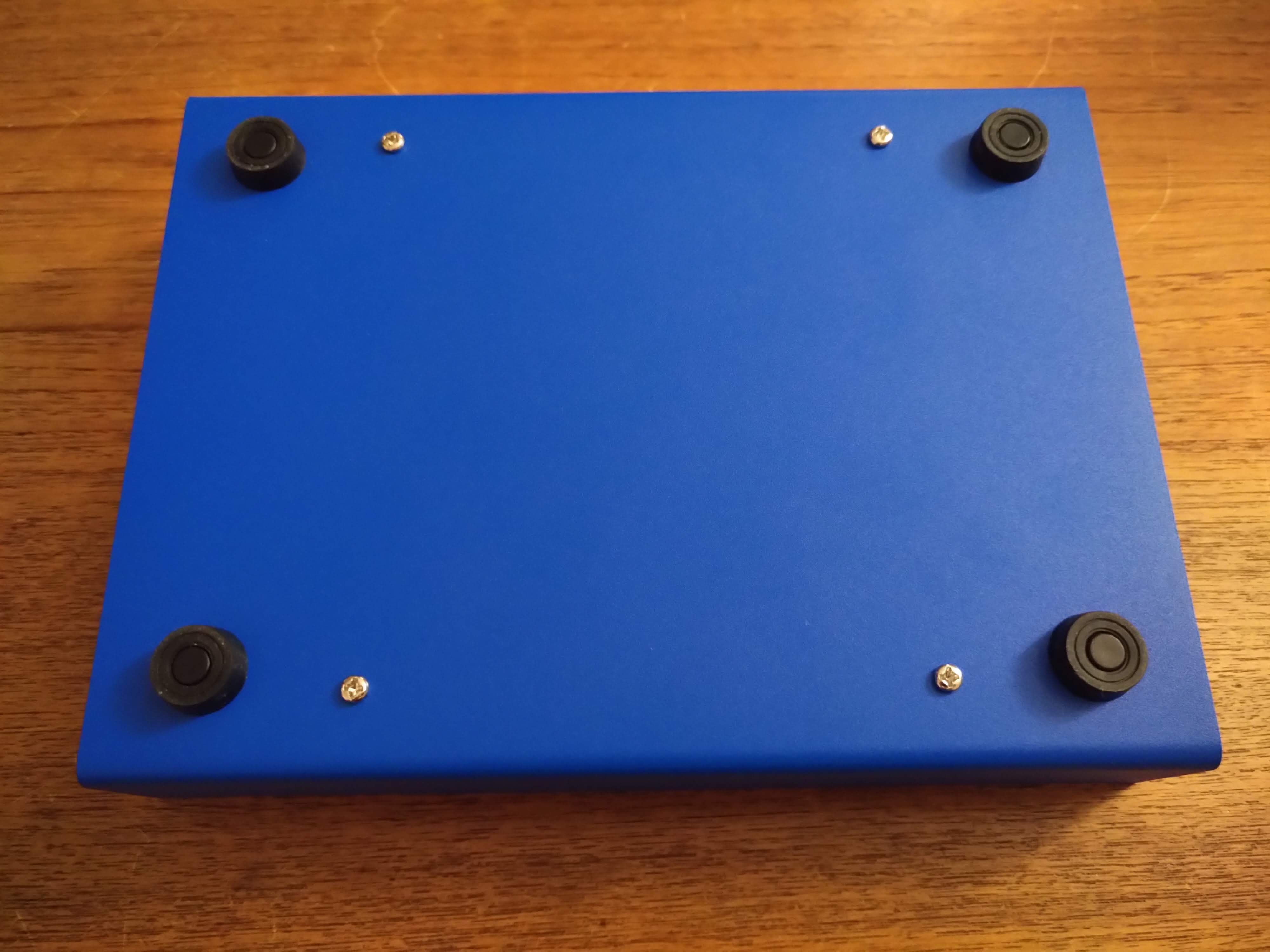
Figure 7. Bottom of the case
I mounted the circuit board on hexagonal brass standoffs. It sits very securely! In the future I would like to be able to stack more boards on top of the main one. (I've been thinking about making it work on more bands.)
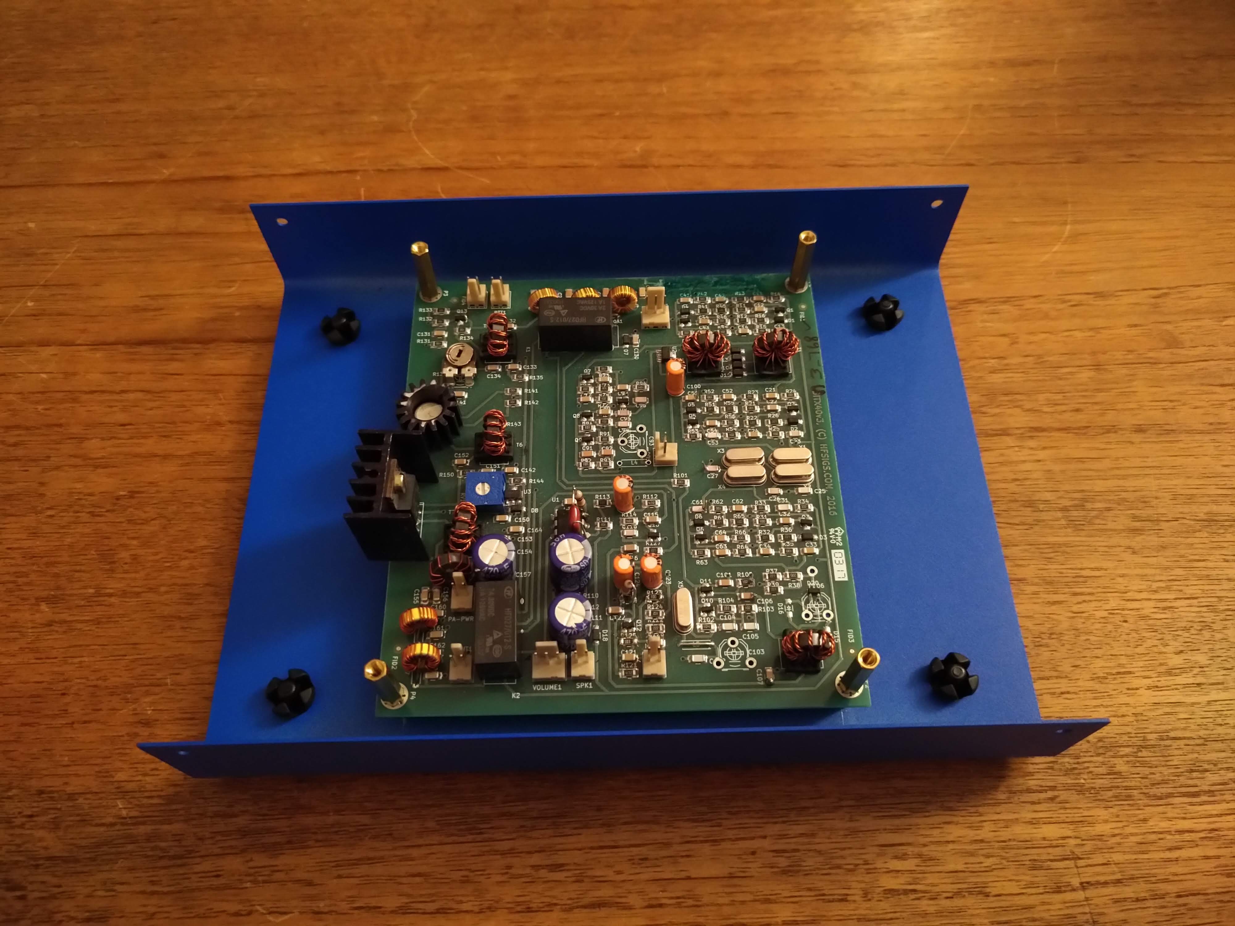
Figure 8. The BITX circuit board mounted in the case
I've just started wiring up everything. Previously I used the wires that came with the kit. I had twisted pairs of wires to reduce interference. This time I will use shielded cable for the headphone and microphone signals as well as RG316 coaxial cable for the VFO and antenna signals.
The Raduino is a small board that sits on the back of the display. The original one is a simple VFO made from an Arduino Nano, a potentiometer for input, and an Si5351 for frequency synthesis. Allard Munters PE1NWL has since added many new features in his sophisticated variant of the Raduino software.
Many of the new features require hardware modifications and I plan to apply most of them. That means a few extra components and a lot of extra wires than need to be attached down to the connectors on the back of the Raduino. To manage that I desoldered the connectors, added pin headers, and soldered a prototype board on the back of the Raduino. That way there should be plenty of room for attaching the new wires and adding the extra components.
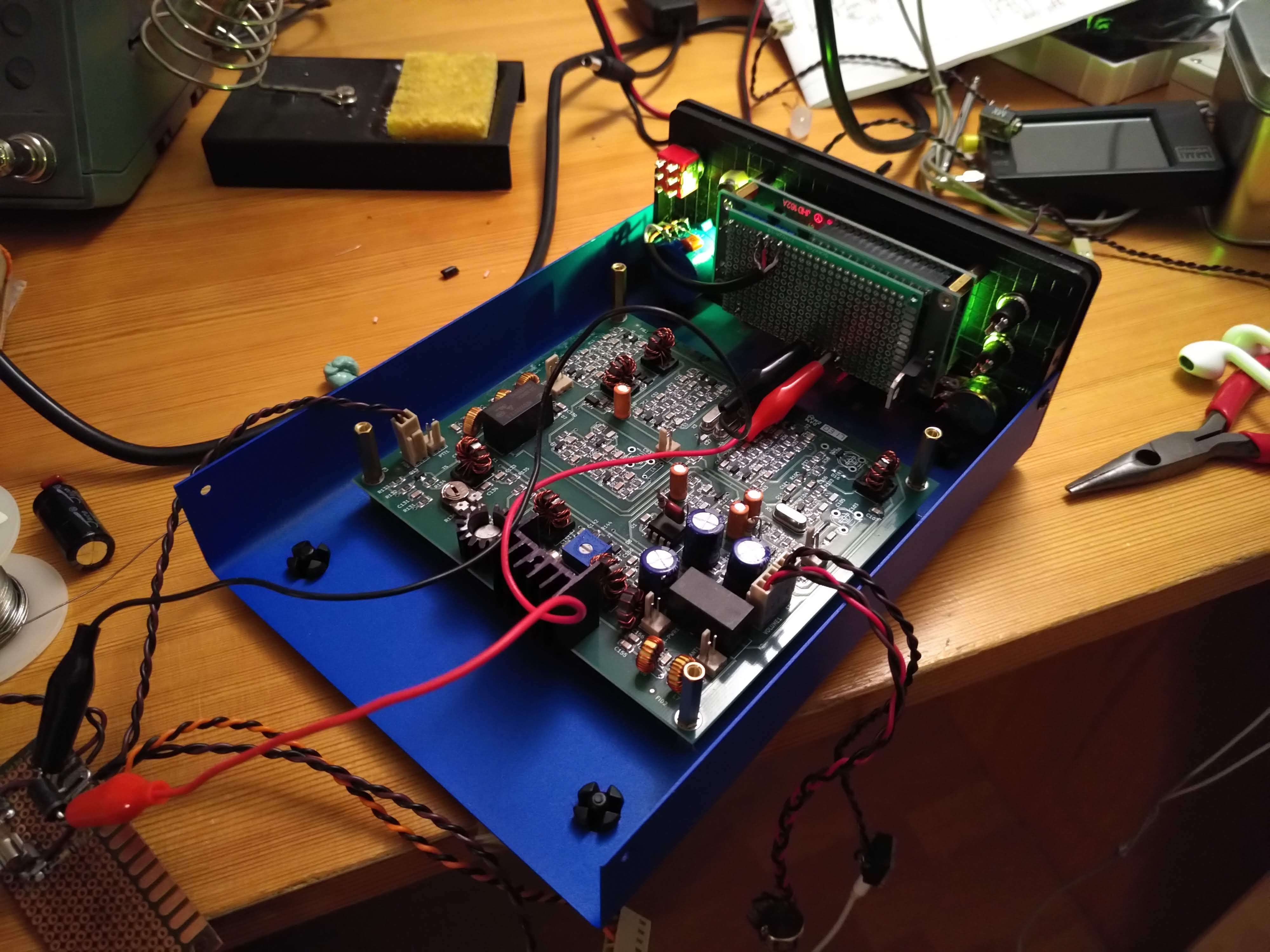
Figure 9. Testing (the lack of) extra voltage regulator capacitors on the Raduino
At the moment I'm experimenting with fixing the well known "tuning tick" problem of the BITX40. The Raduino needs more power filtering. Otherwise loud clicks are heard whenever the frequency is adjusted. Now that I have the extra protoboard I decided to redo my previous fix and add the components to the board instead.
Comments
Comments are hosted on the same server as this blog. The server resides in the EU and no data is shared with third parties.